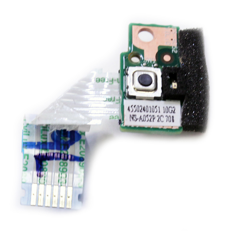
Power Switch Board for LENOVO T440 T440S T450 T460 NS-A052

Popularity (1046 customers like it)
PCS pcspare.com
ID: PCS-10338 Model/PN: NS-A052 Condition: NEW
Availability: In Stock
‌EUR € 3.14
Bulk Quote
  • Guaranteed to fit your DC power board NS-A052
  • Free step-by-step repair guide File
  • Tracked shipping & easy returns

Power / Switch Board — PCB Layout

Cap Connector SW ① Cap ② Conn. ③ Switch ④ Screw How It Works PCB manages power delivery and button inputs (power / volume / assist). FFC cable connects board to motherboard for signal transmission. Match PCB shape, button layout, and connector type.

Frequently Asked Questions & Solutions

Is this board a direct replacement?

This board is designed for NS-A052. Check the part number on your original board to confirm compatibility. Look for the printed board number (e.g., LS‑8391P) and physical button layout – they must match exactly.

How to replace the switch / power board step by step?

  1. Safety first: Disconnect the main battery cable from the motherboard to avoid short circuits or damage to the embedded controller.
  2. Remove the bottom cover (D‑cover) and any necessary shielding to access the board.
  3. Locate the board – it is usually mounted on the upper chassis (C‑cover / palmrest) near the top‑right corner, on the side edge, or close to the DC jack.
  4. Disconnect the flexible cable (FFC or ribbon) from the board by gently flipping up the ZIF locking tab and pulling the cable out.
  5. Unscrew the board (usually 1‑2 small Phillips screws) and lift it out of its recessed cavity.
  6. Install the new board in the same cavity, align the screw holes, and secure it with the screws – do not overtighten.
  7. Reconnect the FFC – insert it fully into the ZIF connector with the correct orientation (gold contacts facing the locking tab), then press the tab down.
  8. Route the cable neatly along the original grooves to avoid pinching when reassembling.
  9. Test functionality – connect the battery briefly, press the power button to see if the laptop boots, and test any side buttons (volume, Novo, etc.).
  10. Power off, disconnect the battery again, and reassemble the covers.

If the board includes status LEDs, ensure they light up as expected during testing.

Where is the switch / power board located inside the laptop?

The board is almost always mounted on the upper chassis (C‑cover / palmrest assembly) or the side frame of the laptop. Common positions include:
  • Top‑right or top‑left corner of the keyboard deck (near the hinge) – the most common location for the main power button.
  • Side edges (left or right) – often used for volume buttons or dedicated assist keys (e.g., Lenovo Novo button).
  • Near the DC power jack – on some models, the power board is integrated with the charging port.
  • It fits into a dedicated recessed cavity and is secured with small screws and/or alignment pins.

Access usually requires removal of the bottom cover only, but some models may need the keyboard or upper bezel to be removed first.

Where does the board's cable plug into the motherboard?

The board connects to the main system board (motherboard) via a flexible flat cable (FFC) or ribbon cable. The motherboard header is usually clearly marked with a silkscreen label such as:
  • SW / SW1 (for power switch)
  • PWR_SW / PWRBTN
  • KB_BL (if backlight control is integrated)
  • IO_BOARD or SUB_BOARD

Connection procedure: Flip up the ZIF locking tab on the motherboard connector, insert the flat cable fully (gold pins facing the correct direction – usually towards the tab), then press the tab down to secure it. No force is required – if it doesn't slide in easily, check orientation.

Important: The cable is delicate – do not bend it sharply or fold it.

What precautions should I take when replacing this board?

  • Always disconnect the battery first – even a small residual charge can short‑circuit the board or corrupt the embedded controller firmware.
  • Handle the FFC with extreme care – avoid creasing, tearing, or pulling on the cable. Always pull by the connector, not the wires.
  • Check orientation – ZIF connectors are keyed; inserting the cable upside‑down will not work and may bend pins if forced.
  • Screw torque – do not overtighten; snug is enough. Over‑tightening can crack the PCB or strip the chassis threads.
  • Avoid ESD – ground yourself (touch a metal surface) before handling the board to prevent static damage.
  • Test before full reassembly – connect the battery, press the power button, and confirm boot‑up. Also test any side buttons (volume/assist) to ensure proper switching.

Troubleshooting if the button does not work:

  • Re‑seat the cable on both ends – sometimes it is not fully inserted.
  • Check for bent pins on the connectors.
  • Verify that the board model matches your laptop's region (some have different key layouts).
  • Reset the EC (Embedded Controller) by unplugging the battery and CMOS battery for 30 seconds.